PID Feedback Controllers
This application note discusses the purpose and principles of controllers by considering the action of a PID controller as a prototypical example on the transfer function of a feedback loop. Beyond that TOPTICA´s PID controllers will be discussed regarding specifications and typical applications.
The purpose of a controller can be understood in the context of general control theory. This is a rather old field and a plethora of text books have been written which fully cover this topic, e.g. the book by R. C. Dorf and R. H. Bishop gives a good overview for a physicist´s practical point of view. Therefore, this application note only gives a short summary of important aspects relevant for the topic of controllers. Figure 15 shows a closed loop diagram typically considered in control theory. It is related to Figure 1 which summarizes the general concept of phase and frequency locking of lasers. r(t), e(t), u(t) and y(t) are the time-dependent reference, error signal, control signal and output signal, respectively. d(t) describes noise which perturbs the system. The time-independent quantities C(s), P(s) and F(s) denote the action of the controller, the plant (in this series of application note it is called “Actuators”) and the sensor, respectively. In this series of application notes F(s) includes the optical setup and the opto-electronic sensor described in the application note “Error Signal Generation”. Analysing this system using the Laplace transforms R(s), E(s), U(s),Y(s) and D(s) of the variables r(t), e(t), u(t),y(t) and d(t), yields the relation
\(Y(s)=\left( \frac{P(s)C(s)}{1+P(s)C(s)F(s)} \right)R(s)+\left( \frac{1}{1+P(s)C(s)F(s)} \right)D(s)=T(s)R(s)+S(s)D(s)\)
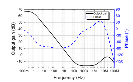
between the reference signal, the noise entering the system and the output signal. \(T(s)=\frac{P(s)C(s)}{1+P(s)C(s)F(s)}\) is called the reference transfer function of the feedback loop, \(S(s)=\left( \frac{1}{1+P(s)C(s)F(s)} \right)\) is the disturbance transfer function, while C(s) is the transfer function of the controller. An example of C(s) is shown in Figure 16. From this relation two important statements can be derived. First, for a large gain C(s) of the controller and \(|F(s)|\approx 1\) the output signal closely follows the reference signal and disturbances are suppressed effectively. Second, if the overall phase of the product P(s)C(s)F(s) (phase delay) reaches 180°, then the magnitude of the denominator 1+P(s)C(s)F(s) can become very small and the feedback loop starts amplifying deviations from the reference value instead of damping them. From these statements two key requirements for the controller can be formulated. First, the parameters of the controller should be chosen such that the phase of the product P(s)C(s)F(s) has a value between -90° and +90° up to a frequency sbwas large as possible. Second, the magnitude of the product P(s)C(s)F(s), i.e. the gain of the feedback loop, should be much larger than 1 for values of s smaller than the loop bandwidth sbwas large as possible. Second, the magnitude of H(s), i.e. the gain of the feedback loop, should be much larger than 1 for values of s smaller than the loop bandwidth sbw, while it should be much smaller than 1 for frequencies s larger than the loop bandwidth.

The PID controller is the prototype for most controllers, where the P, I and D represent different parts of the controller which contribute to the control signal u(t).The overall signal is the sum of these three parts. The P stands for the proportional part and contributes to the control signal u(t) a term which is proportional to the error signal \(K_p\cdot e(t)\). The I stands for the integral part and contributes a term which is proportional to the integral of the error signal \(K_I\int_0^t{d\tau\; e(\tau)}\). The D stands for the derivative part of the controller and contributes a term which is proportional to the derivative of the error signal \(K_D\cdot \frac{de(t)}{dt}\). The control signal u(t) is given by the sum of these three parts
\(u(t)=K_p\cdot e(t)+K_I\int_0^t{d\tau\; e(\tau)+K_D\cdot \frac{de(t)}{dt}}\)
Applying the Laplace transformation to this equation yields the controller transfer function
\(C(s)=K_p+\frac{K_I}{s}+K_Ds\)
While \(K_I\) can be used to adjust the transfer function for lower frequencies, \(K_D\) has an impact on the high frequency part of the transfer function. \(K_p\) acts on the intermediate frequency range. Beyond that, considering the relation \(s=2\pi i\cdot f\), this equation shows that the integral part induces a phase shift of -90°, while the derivative part introduces a phase shift of +90°.
Most controllers are a combination of these three elements. However, there are several ways how to combine and physically implement these elements. Consequently, there is a large variety of controllers with different features available. But what defines a good controller? This depends on the requirements of the application. In the following, several criteria relevant for laser locking will be discussed.
One of the most important benchmarks is the bandwidth of the controller defined above. Intuitively it can be understood as the rate at which deviations from the set value can be corrected. If the laser linewidth is of critical importance, a controller with a bandwidth as high as possible should be chosen. The bandwidth of the controller should be understood as an upper limit of the possibly achievable bandwidth of the feedback loop. Typically, the actual bandwidth of the feedback loop will be significantly smaller. Related to the bandwidth is the signal delay of the controller which describes how much time it takes for a signal to be transferred from the input to the output of the controller.
Another important criterion is convenience. Many applications require remote control of laser systems. To realize this, controllers with a digital interface are typically preferred over purely analog ones because in many cases they feature a software interface which allows remote control. Beyond that, more sophisticated features like automatic relocking and signal analysis can be implemented more easily.
TOPTICA offers a variety of controllers which address different requirements. Table 1 gives an overview of TOPTICA controllers and their characterization in terms of bandwidth and convenience.
| FALC pro | DLC pro Lock | DigiLock 110 | |
| Description | High-performance solution for linewidth reduction; digital interface (remote locking) | Digital controller (integrated in DLC pro); High convenience (Relock, Click&Lock) | Versatile digital locking solution + analysis features |
| Bandwidth | 50 MHz (-3 dB) | ≈ 30 kHz | ≈ 10 MHz (analog) |
| Signal Delay (typ.) | 10 ns | 10 µs | 200 ns (digital) |
Table 1: Overview of controllers offered by TOPTICA.
The DLC pro lock is a digital lock based on a field-programmable gate array (FPGA) and reaches bandwidths of up to 30 kHz. It excels in terms of convenience and ease of use as it provides remote locking and features like automatic relock. The so-called click&lock function lets you easily choose your set point by just clicking on it on the touchscreen of the DLC pro. It offers the possibilities of side-of-fringe and top-of-fringe locking and is thus an excellent choice for realizing a spectroscopy lock. On top of that it includes a feature which automatically optimizes the lock using an algorithm which analyses the response of the feedback loop and thus finds the optimal PID parameters.
The FALC pro is a high-performance controller with unrivalled bandwidth and signal delay. It is the perfect choice for reducing the laser linewidth, e.g. by realizing a PDH lock on a high-finesse cavity in combination with the PDH/DLC pro module. While it is an analog controller and thus reaches extremely low signal delays of typically 10 ns, it features a digital interface, which is responsible for its very convenient usability. It allows remote locking and combining it with the DLC pro lock enables the automatic relock and the click&lock function. It also includes a frequency mixer and thus is the perfect choice to implement an offset phase lock. The FALC pro is the successor of the FALC 110 and the mFALC 110.
The DigiLock 110 is the combination of a digital and an analog controller which makes a high bandwidth of up to 10 MHz possible while offering various analysis features. With the parameters given, the DigiLock can calculate the controller frequency response in amplitude and phase and visualize it, which is a useful tool in optimizing locking performance. Beyond that the DigiLock offers network analysis functions for determining actuator bandwidth and resonance frequencies.