Error-Signal Generation
This application note deals with the question of how to generate an error signal for phase and frequency stabilization of lasers. First, general schemes which are independent of the choice of reference are discussed. After that, schemes based on the references discussed in the application note "Frequency References" are presented.
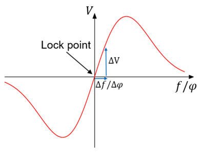
The goal of error signal generation is to create an electronic signal that is proportional to the laser´s deviation from a certain set frequency or phase which will be called lock point in the following. Figure 4 shows what such an error signal could look like. If the laser frequency is too small, the signal is negative. If its frequency is too large, the signal is positive and it is zero at the lock point. A requirement for a good frequency stabilization is a large signal-to-noise ratio, i.e. small frequency deviations should cause a large signal. Considering Figure 4 this means that the steepness of the slope around the lock point is desired to be large.
In this application note, it is discriminated between locking the phase and locking the frequency. In principle the result is equivalent because if the phase offset is constant over time, then the frequency offset will be as well. However, laser locking based on an error signal which is a function of a laser´s frequency deviation will be referred to as frequency locking while laser locking based on an error signal which is a function of a laser´s phase deviation will be referred to as phase locking. The difference will become clear in the following examples.
Quite generally, generating an error signal consists of two steps. The first step is to create an optical signal using an optical setup involving a reference, e.g. one of those presented in the application note “Frequency References”.This is necessary because visible light exhibits frequencies around several hundreds of THz which makes it impossible to directly convert this into an electronic signal with the same frequency. Therefore, using the reference, the optical signal is converted to lower frequencies which are directly detectable. Consequently, the second step is to record the optical signal using e.g. a photo-diode or a camera and subsequently to further process this signal electronically.