General Error-Signal Generation Schemes
a) Side-of-fringe locking
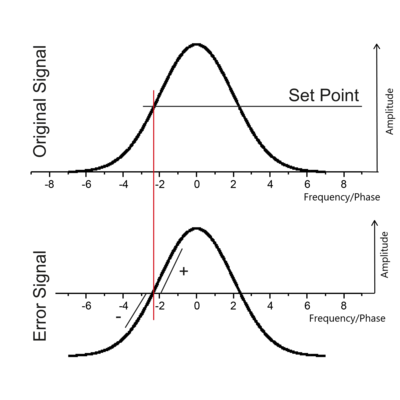
Considering a spectral peak, e.g. obtained from the transmission through a spectroscopy cell or through an optical resonator, a straight forward way to obtain an error signal is to add or subtract a constant offset. Figure 5 illustrates this scheme. Then there will be two zero crossings, one at the left and the other at the right side of the peak. In the vicinity e.g. of the left zero crossing, the signal will be positive if the frequency is larger than the frequency at the zero crossing and the signal will be negative if the frequency is smaller than the frequency at the zero crossing. Consequently this can be used as an error signal for stabilizing the laser to the frequency at the zero crossing. Because the laser will be locked to the side of the peak, this locking scheme is called side-of-fringe locking. A problem of this scheme is that amplitude fluctuations will cause the position of the zero crossing to fluctuate, i.e. the lock will convert amplitude noise of the laser into frequency noise which is undesirable. It is important to note that side-of-fringe locking is naturally limited to frequencies above or below the spectral feature. It is a natural consequence of this particular locking scheme that locking the laser exactly on the spectral feature is impossible.
b) FM spectroscopy and top-of-fringe locking
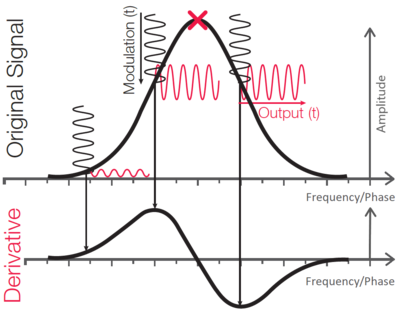
An alternative method is based on the principle of frequency modulation (FM) spectroscopy. The laser frequency is modulated, e.g. by modulating the laser current or with an EOM. As the frequency is scanned over a spectral feature, the frequency modulation will be converted into an amplitude modulation (AM). Assuming modulation amplitudes smaller than the width of the spectral feature, the amplitude of this signal will be proportional to the slope of the spectral feature at the centre frequency of the modulation. This relation is shown in the upper plot of Figure 6. Using the lock-in detection principle, this AM signal can be demodulated by mixing it with the radio frequency (RF) used for modulating the laser frequency or the phase of an EOM. This yields a DC signal whose dependence on laser frequency is shown in the lower plot of Figure 6. It is proportional to the slope of the spectral feature. It has all desirable features of an error signal as described earlier and can be used to lock the laser frequency to the top of the peak. Therefore, this scheme is also referred to as top-of-fringe locking.